
Multi-band MIMO-ODAS
LTE1800 and LTE2600
MIMO-ODAS uses low power optical laser and RF signal transmission which is environmental friendly.
Features
- MIMO and multi-bands system that supports frequency from 800MHz to 2700MHz.
- Either single mode or multi-mode optical fiber cable is used as the transmission line. The maximum optical fiber cable length is up to 6km and 500m respectively.
- Each optical fiber cable carries multi-bands and duplex signal.
- Low noise figure and zero losses in the optical fiber cable linkbudget calculation that allows very large area coverage by installing long optical cable fiber run and disturbing many ORU.
- Low RF power transmission at the ORU enables smaller cell coverage for improving traffic capacity and also reduces any possible signal interferences and noise to the neighboring cells.
- 0dB to 20dB (gain @1 dB step) is controllable at the MIMO-ODAS to base station and separately, 0dB to 15dB attenuation at the ORU, these allow optimization of the overall system performance for different environment and coverage area.
- Simple and easy system design and installation of it’s 2 levels Star Topology network configuration. It also allows easy trouble-shooting since each system element and network branch works independently.
- Remote monitoring and alarms system via SMS network.
Typical Network Installation for In-Building Coverage Solution
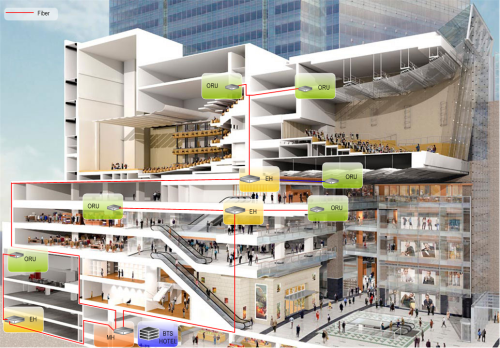
The above figure shows a typical deployment of MIMO-ODAS in very large building where cellular coverage is needed for the auditorium, function hall, retail shop, lobby and carpark. The ORU is extensively and evenly distributed inside the building to provide RF coverage. EH is used to extend the MH 1:8 optical distributions, it makes the installation easier and reduces the numbers of optical fiber cable going back to the MH. Both MH and EH is a typical 19” rack enclosure whereas ORU is designed to be smaller form factor for easy installation on the wall or even inside and above the false ceiling. MH is installed with the base station in a centralized location.
In comparison to a passive DAS, MIMO-ODAS is simpler, easier and faster to install. The total cost of ownership is lower especially for a MIMO DAS network. It is better in the radio performance. The network is future proof against the dynamic changes and improvement of wireless communication system. Last but not least, it allows remote monitoring and alarm notification of each ORU, therefore, customer care can address any faults and complaints with good knowledge of the network health status and maintenance team can resolve the faults immediately.
Star Network Topology
The simplest network configuration of MIMO-ODAS consists of 1xMH, 1xEH and 1xORU (1-1-1). One MH can connect up to 8xEH and 1xEH can connect up to 8 ORU, therefore each branch has a maximum configuration of up to 64xORU (1-8-64). This is sufficient to provide an extensive coverage for a typical size building.
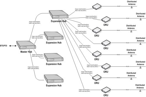
MIMO-ODAS is made up of the following:
- MH (Main Host): It is connected to the base station or POI via co-axial cable. It’s main function is to convert electrical signal into optical signal and vice versa between the MH and EH. 1xMH can connects up to 8 xEH;
- EH (Extension Hub): It is an intermediate point that transports the optical signal between the MU and ORU. 1xEH can connects up to 8xORU;
- ORU (Optical Remote Unit): It is connected to the antenna to provide RF coverage. It’s main function is to convert optical signal into electrical signal and vice versa between the EH and antenna port;
- Remote monitoring and alarm system: Each MU is used as the main interface to monitor and control the EH and ORU. The operations status and alarms are enquired via SMS, 3G/GSM modem.
Applications
- Campus
- High-rise Building
- Hotel
- Expo Hall
- Inside Lift Car
- Integrated Resort
- Shopping Mall
- Airport Terminal
- Stadium
- Underground Tunnel
Monitoring and Alarm Features
MIMO-ODAS provides 3 ways of monitoring and alarm:
- Using LED light indicator at each system element to provide on-site monitoring and alarm warning. For example, if one of the ORU is faulty, the ORU will show red light. At the same time, red light will turn on at the EH and MH to indicate which linked ORU is faulty.
- Dry contact alarm connection: MH has dry contact alarm connection to provide alarms to base station alarm system.
- Operation status, alarms and faults: User simply needs to connect to internet to monitor and control the system. In addition, alarms can be notified via SMS to a group of people.
